Difference between revisions of "Jatco JF011E Stepper Motor Testing"
Cartman02au (talk | contribs) |
Cartman02au (talk | contribs) |
||
| (6 intermediate revisions by the same user not shown) | |||
| Line 1: | Line 1: | ||
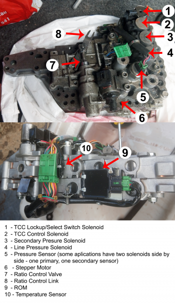
| − | The Jatco JF011 CVT transmission | + | [[Image:F1CJA Valve Body.png|right|350px]]The Jatco JF011 CVT transmission, referred to by Mitsubishi as the [[F1CJA]] and W1CJA) is known for having a number of issues. One of the most common problems with the transmission is the failure of the stepper motor. When the stepper motor fails, you will receive a '''P1777''' error indicating an electrical malfunction with the stepper motor. |
| − | + | The Mitsubishi service manual guides you through testing the motor windings and the wiring before recommending you replace the entire transmission valve body if the electrical side checks out OK. | |
| − | + | The stepper motor (6) is located on the top side of the transmission valve body and assists in selecting the gear ratio in use by moving the Ratio Control Link (8) which sets the position of the Ratio Control Valve (7). | |
| − | [[Image:F1CJA_Stepper_pinout.png|left|200px|thumb|Stepper motor pinout]]The stepper motor is a unipolar two winding type with six wires going into it. Each winding has three wires running into it, with the black wires at pins 2 and 5 being the ground. | + | ===Electrical Tests=== |
| + | [[Image:F1CJA_Stepper_pinout.png|left|200px|thumb|Stepper motor pinout]] | ||
| + | |||
| + | The stepper motor is a unipolar two winding type with six wires going into it. Each winding has three wires running into it, with the black wires at pins 2 and 5 being the ground. | ||
To test the stepper motor windings, using a ohmmeter check the resistance between the following pins:<br> | To test the stepper motor windings, using a ohmmeter check the resistance between the following pins:<br> | ||
| Line 15: | Line 18: | ||
4 and 6 = 30 ohms<br> | 4 and 6 = 30 ohms<br> | ||
| − | If | + | If the values are within 5 ohms of these, the stepper motor windings are OK. |
| + | |||
| + | ===Motor Movement=== | ||
| + | [[Image:Jatco_Movement_Tester.png|left|500px|thumb|Stepper Motor Movement Tester Schematic]] | ||
| + | To check the movement of the stepper motor you will need to use a stepper motor controller. As the motor uses six wires, it can be driven in either unipolar or bipolar mode. You can create a simple stepper motor tester using an Arduino Uno, Duinotech XC4492 module (which uses the L298 chip) and a power supply. | ||
| + | |||
| + | The transmission control module drives the motor at 5 volts so a 5 volt 0.5 amp power supply would be ideal. The motors will still work on a test bench at 12 volts but do seem to heat up a little. | ||
| + | |||
| + | {{Clear}} | ||
| + | ====Arduino Code==== | ||
| + | <syntaxhighlight lang="C"> | ||
| + | // Include the Arduino Stepper Library | ||
| + | #include <Stepper.h> | ||
| + | |||
| + | // Number of steps per output rotation | ||
| + | const int stepsPerRevolution = 320; | ||
| + | |||
| + | // Create Instance of Stepper library | ||
| + | Stepper myStepper(stepsPerRevolution, 8, 9, 10, 11); | ||
| + | |||
| + | |||
| + | void setup() | ||
| + | { | ||
| + | // set the speed at 15 rpm: | ||
| + | myStepper.setSpeed(15); | ||
| + | // initialize the serial port: | ||
| + | Serial.begin(9600); | ||
| + | } | ||
| + | |||
| + | void loop() | ||
| + | { | ||
| + | // step one revolution in one direction: | ||
| + | Serial.println("clockwise"); | ||
| + | myStepper.step(stepsPerRevolution); | ||
| + | delay(500); | ||
| + | |||
| + | // step one revolution in the other direction: | ||
| + | Serial.println("counterclockwise"); | ||
| + | myStepper.step(-stepsPerRevolution); | ||
| + | delay(500); | ||
| + | } | ||
| + | </syntaxhighlight> | ||
[[Category: CVT Transaxles]] | [[Category: CVT Transaxles]] | ||
Latest revision as of 03:13, 13 September 2020
The Jatco JF011 CVT transmission, referred to by Mitsubishi as the F1CJA and W1CJA) is known for having a number of issues. One of the most common problems with the transmission is the failure of the stepper motor. When the stepper motor fails, you will receive a P1777 error indicating an electrical malfunction with the stepper motor.
The Mitsubishi service manual guides you through testing the motor windings and the wiring before recommending you replace the entire transmission valve body if the electrical side checks out OK.
The stepper motor (6) is located on the top side of the transmission valve body and assists in selecting the gear ratio in use by moving the Ratio Control Link (8) which sets the position of the Ratio Control Valve (7).
Electrical Tests
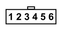
The stepper motor is a unipolar two winding type with six wires going into it. Each winding has three wires running into it, with the black wires at pins 2 and 5 being the ground.
To test the stepper motor windings, using a ohmmeter check the resistance between the following pins:
1 and 2 = 15 ohms
2 and 3 = 15 ohms
1 and 3 = 30 ohms
4 and 5 = 15 ohms
5 and 6 = 15 ohms
4 and 6 = 30 ohms
If the values are within 5 ohms of these, the stepper motor windings are OK.
Motor Movement
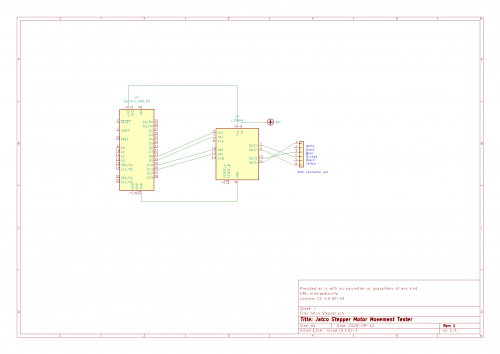
To check the movement of the stepper motor you will need to use a stepper motor controller. As the motor uses six wires, it can be driven in either unipolar or bipolar mode. You can create a simple stepper motor tester using an Arduino Uno, Duinotech XC4492 module (which uses the L298 chip) and a power supply.
The transmission control module drives the motor at 5 volts so a 5 volt 0.5 amp power supply would be ideal. The motors will still work on a test bench at 12 volts but do seem to heat up a little.
Arduino Code
// Include the Arduino Stepper Library
#include <Stepper.h>

// Number of steps per output rotation
const int stepsPerRevolution = 320;

// Create Instance of Stepper library
Stepper myStepper(stepsPerRevolution, 8, 9, 10, 11);


void setup()
{
  // set the speed at 15 rpm:
  myStepper.setSpeed(15);
  // initialize the serial port:
  Serial.begin(9600);
}

void loop()
{
  // step one revolution in one direction:
  Serial.println("clockwise");
  myStepper.step(stepsPerRevolution);
  delay(500);

  // step one revolution in the other direction:
  Serial.println("counterclockwise");
  myStepper.step(-stepsPerRevolution);
  delay(500);
}

